
As an industrial designer, I have been using 3D CAD to develop designs and fully engineer products for manufacture. Creo and SolidWorks are my preferred CAD software.
At Gm design Development, we undertake all aspects of product design, from concept generation to production and we use 3D CAD extensively.
Key area we are experts in are:
Advanced Surface modelling
We begin the development of each product by defining a skeleton or master model. We develop this as surfaces, creating sophisticated/ pure form using advanced surface modelling. This delivers products with preferred and accurate form, whether for aesthetics or for ergonomics.
Top-down-modelling technique
Everything is driven by the master model, with it being at the top level. Internal components/ subassemblies are developed from this. It ensures design intent is maintained if different teams are developing the product. In my experience, it also produces more robust 3D CAD models and assemblies.
Designing & defining injection moulded products
Using the master model, relevant geometry and features are exported to each part. Ie. Upper, lower moulding for example. The CAD for these mouldings is further developed, solidified and then all the internal details are defined. As the parts are driven by the master, we can finesse the form of the master, and this will drive and be reflected in the individual components. Axis and datum planes included in the master model can also be adjusted. This ensures correct alignment of screw bosses for example and eliminates potential errors.
Draft angle – optimised for injection moulding
For the main form of the product, draft angle is generated as an inherent part of the product form when we define the surfaces. I use various techniques to ensure draft angle is maintained around the split line, particularly important when modelling surface boundaries where draft angles can vary if not controlled. This means we produce a shelled moulding that is naturally fully drafted. Then as details are added, internal draft can be added where necessary.
Electronic mechanical assembly – 3D CAD
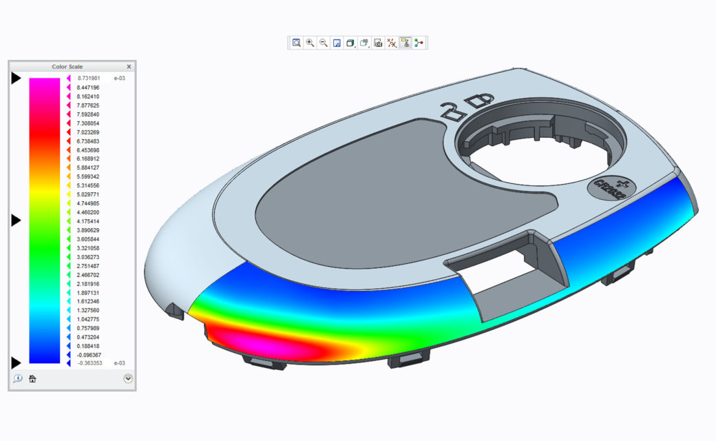
We import the electronic definition into our assemblies, either as a 3D model or we may important a DXF 2D layout and then define the physical components. Interference checks can be carried out to ensure components do not clash with the other components.
2D component drawings
We produced fully dimensioned 2D component drawings from the 3D CAD. These will have all tolerances specified and form a critical part of the manufacture package, along with the 3D CAD data. These are both issued to the toolmaker.
#3DCADservices #3dcadserviceslondon #3dcadservicesuk #3dcadlondon #3dcadUK #3dcad #caduk #londoncad #cad #productdesignuk #productdesignlondon